new comics 2026
Chapter Eleven
Car World
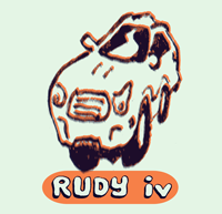
Rudy IV
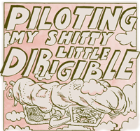
Piloting My Shitty Little Dirigible
Wormwood
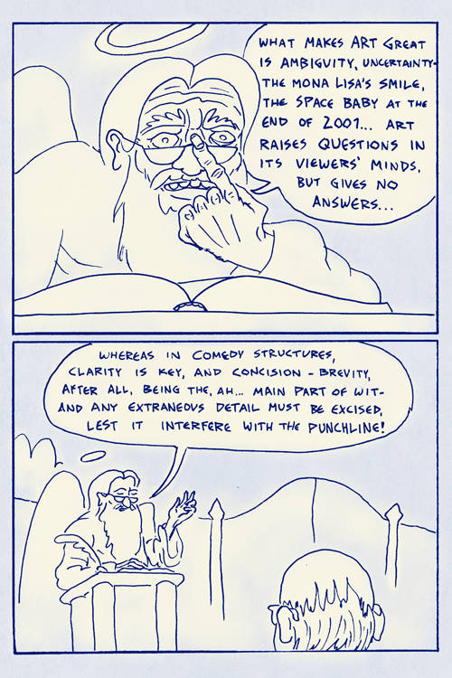
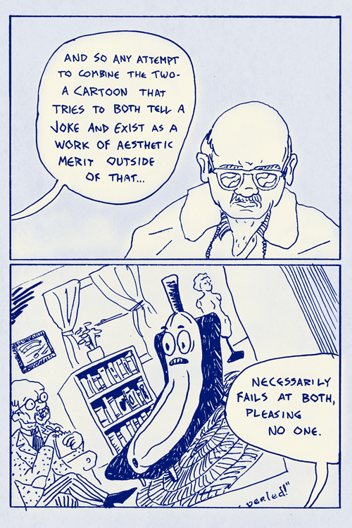
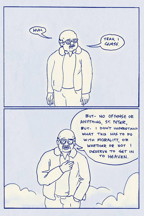
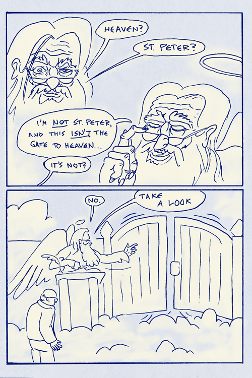
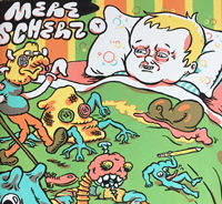
Mere Scherzo
dream comics 2022-2024
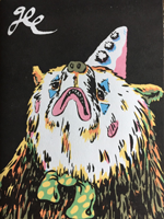
Gee
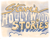
Steve's Hollywood Stories
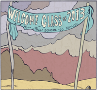
Welcome Class of 2013
Window Unit
New Comics 2022
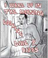
I Wake Up In The Morning Looking Like P. Diddy
New Comics 2021
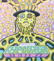
Arachis Hypogaea
Jets n Sprites pt 2
New Comics 2020
dream comics 2018-2021
New Comics 2019
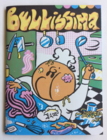
Bellisima
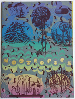
Nootropics
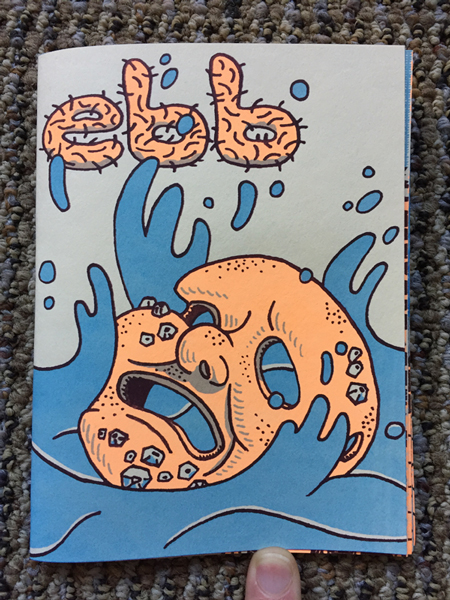
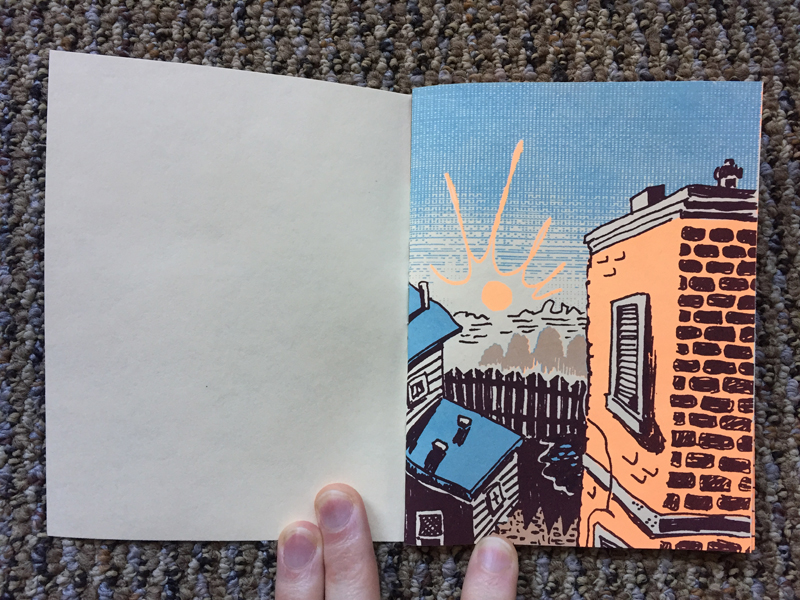
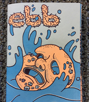
Ebb
Cough
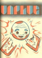
Unplug
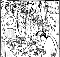
Five Year Plan
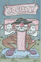
Jail Society 1
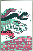
Jets & Sprites
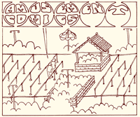
Amusement Comics
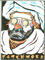
Patchwork
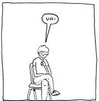
Diary Comics
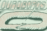
The Ouroboros
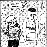
untitled hipster comic
Cyber Life
Tiny Melodramas
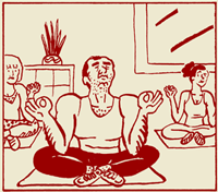
meditation comics
Workplace Domination
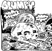
Glumpy
Superhero Comics
Street Gang
Speedy's Pizza
Silt
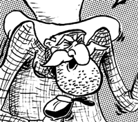
cowboy comics
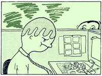
Office Comics
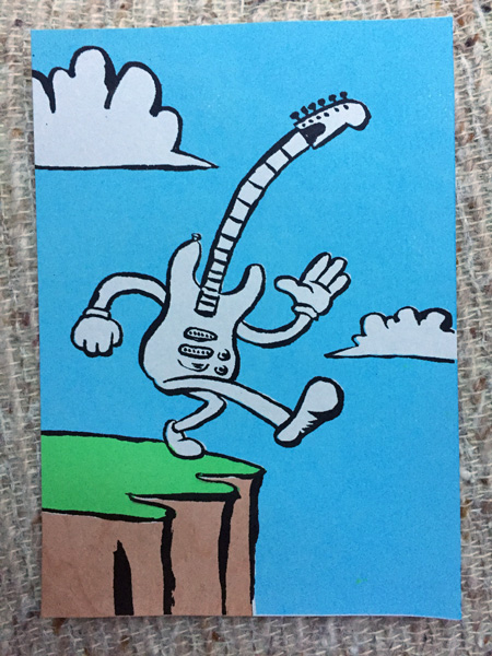
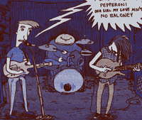
Garage Band Hijinx
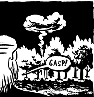
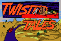
Twisted Tales: Burial Ground
Teen Wizard Academy
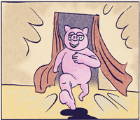
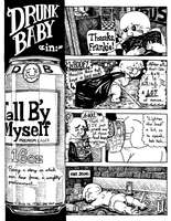
Drunk Baby
big strips
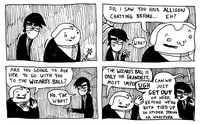
two cool dudes
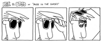
Max n Otto
small strips
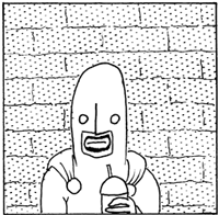
single panel